Package Include:
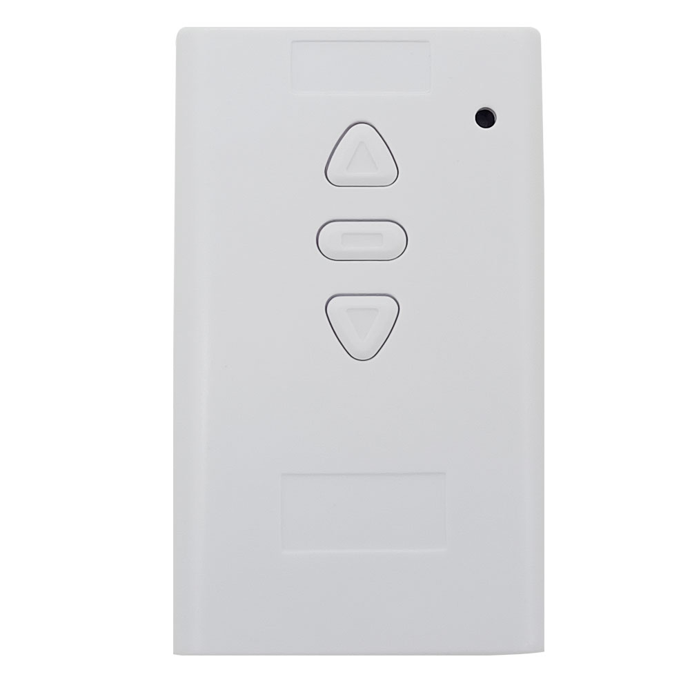
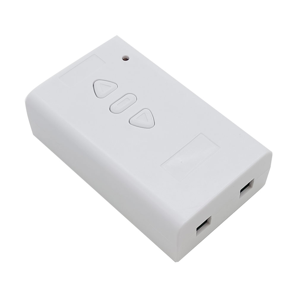
1 x Receiver: S1FC-DC
1 x User manual
Application:
This receiver is a wireless controller for DC motor or linear actuator, it
and the transmitter form a wireless transmitter receiver system. If you
connect a DC motor to this receiver, you can operate the motor to rotate in
positive or reversal direction by the remote control. If you connect a DC
linear actuator to this receiver, you can operate the linear actuator to
extend or retract by the remote control. You can connect two limit switches
to the receiver and use them to stop the motor or the linear actuator. You
also can connect a manual switch to the receiver and use them to control the
motor or the linear actuator.
Features:
Wireless control, easy to install.
Suitable for DC motor or linear actuator.
DC 9~36V operating voltage range.
Two working modes.
You can operate the motor to rotate in positive or reversal direction by using the buttons in the receiver or by the transmitter.
You can operate the linear actuator to extend or retract by using the buttons in the receiver or by the transmitter.
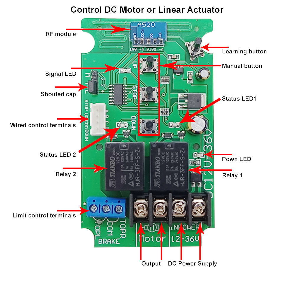
With three manual buttons: You can control the motor or linear actuator by manual buttons.
With limit control terminals: You can connect sensors, limit switches or external devices to stop the motor or the linear actuator.
With wired control terminals: You can connect manual switches to control the motor or linear actuator.
The transmitter / remote can control the receiver from any place within a reliable working distance.
The wireless RF signal from the transmitter can pass through walls, floors, doors, or windows, but it will lose some operating range.
The receiver has reverse power protection and over current protection built in.
The receiver only works with the selected transmitter which is matched to the receiver.
One or more transmitters / remotes can control one or several receivers simultaneously.
Two or more receivers may be used in the same area.
Receiver Parameters:
Model: S1FC-DC
Operating Voltage: 9~36 VDC
Output Voltage: 9~36 VDC same as input voltage
Working Frequency: 433.92 MHz
Channel: 1 CH, can work with 1 DC motor or 1 linear actuator
Quiescent Current: ≤6mA
Rated Current: 10A, so linear actuator or motor's maximum starting current cannot exceed 10A.
Wire range for the terminals: 22-14 AWG
2 Selectable Modes: Interlocking, Momentary
Operating Temperature: -20°C ~ +70°C
Case Size: 100 x 60 x 30 mm (4.0 x 2.4 x 1.2 inches)
Matching Transmitters:
This receiver can work with different transmitters, such as model
CWC-3L
(waterproof, 50 Meter / 150 feet),
C-2-2
or
C-3-2
(100 Meter / 300 feet),
CP-2
or
CP-3
(500 Meter / 1500 feet),
CV-2-2
(500 Meter / 1500 feet),
CG-3
(500 Meter / 1500 feet) or
CB-3-2
(1000 Meter / 3000 feet).
1) When you set the receiver in Momentary mode, it should work with two
button transmitter, such as model CP-2, C-2-2 or CV-2-2.
2) When you set the receiver in Interlocking mode, it should work with three
or four buttons transmitter, such as model CWC-3L, C-3-2, CP-3, CG-3 or
CB-3-2.
Working Range:
This receiver and different transmitters form a complete set, which can
achieve different working distances. For example, when it and the
transmitter CP-3 form a complete set, the maximum working distance may reach
500 meters in an open area. When it and the transmitter CB-3-2 form a
complete set, the maximum working distance may reach 1000 meters in an open
area.
The maximum working distance is based on theoretical data without obstacles
and any RF interference. In practice, it will be hindered by trees, walls,
or other construction, and will be interfered with by other wireless
signals. Therefore, the actual working distance may not reach this maximum
distance.
The receiver equipped with an external antenna has a larger working range
than the receiver equipped with an internal antenna.
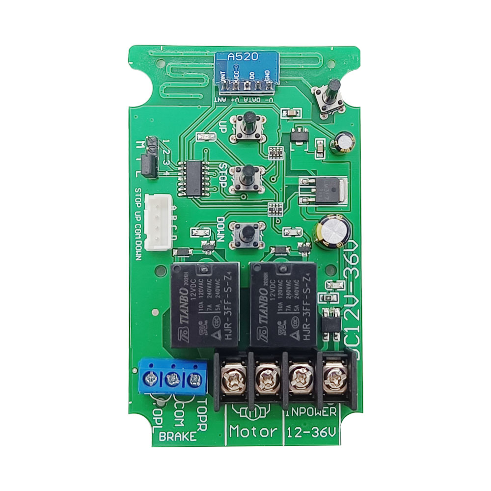
Usage:
The receiver can be used to control DC 12V / 24V motor or linear actuator.
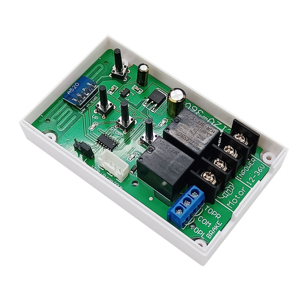
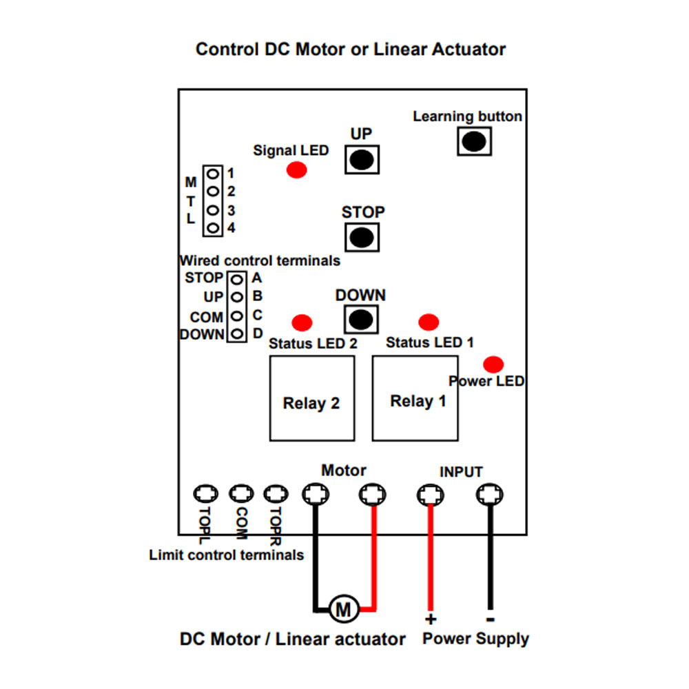
Wiring:
If you want to control a DC 12V / 24V motor or linear actuator, do as
following:
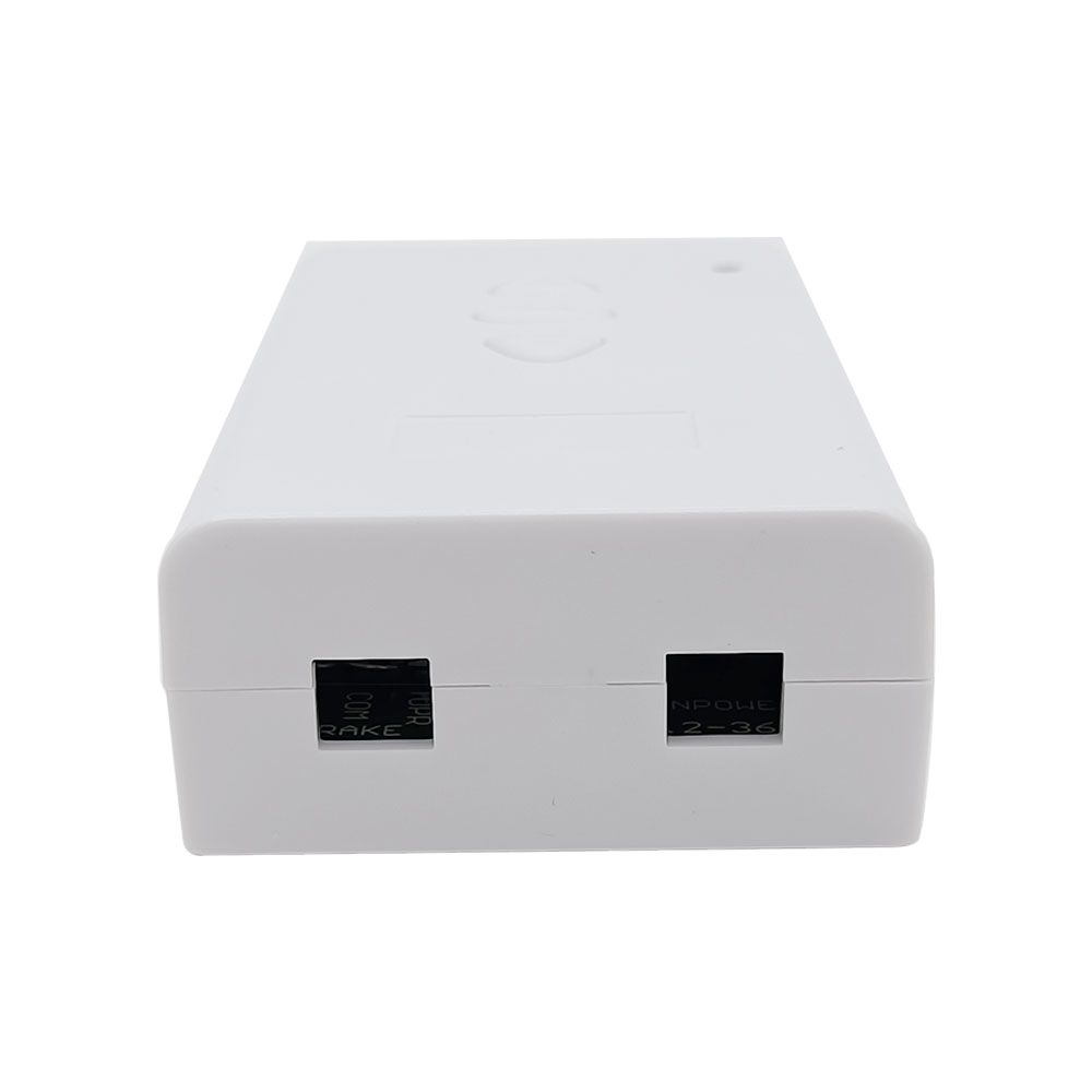
1) Connect the positive pole of DC power supply to terminal <+> of Input,
and connect the negative pole of DC power supply to terminal <-> of Input.
2) Connect two wires of motor or linear actuator to terminals , and
you can exchange these two wires to change the rotating direction of motor
or the moving direction of linear actuator.
Setting different working modes:
The receiver will be set in Interlocking mode before leaving the factory, if
you require momentary mode, please follow the following steps.
Note: Need to restart the receiver after changing the working mode.
1) Setting Interlocking mode: Turn the mode toggle switch in the receiver to position L.
The operation by the transmitter, such as CP-3:
Press the button ▲ on the transmitter: Motor rotates in positive direction,
or linear actuator extends outward.
Press the button ▼ on the transmitter: Motor rotates in reversal direction,
or linear actuator inward retracts.
Press the button ■ on the transmitter: Motor or linear actuator stops.
The operation by the receiver:
Press the button ▲ on the receiver: Motor rotates in positive direction, or
linear actuator extends outward.
Press the button ▼ on the receiver: Motor rotates in reversal direction, or
linear actuator inward retracts.
Press the button ■ on the receiver: Motor or linear actuator stops.
2) Setting Momentary mode: Turn the mode toggle switch in the receiver to position M.
The operation by the transmitter, such as CP-3:
Press and hold the button ▲ on the transmitter: Motor rotates in positive
direction, or linear actuator extends outward.
Release the button ▲: Motor or linear actuator stops.
Press and hold the button ▼ on the transmitter: Motor rotates in reversal
direction, or linear actuator inward retracts.
Release the button ▼: Motor or linear actuator stops.
The operation by the receiver:
Press and hold the button ▲ on the receiver: Motor rotates in positive
direction, or linear actuator extends outward.
Release the button ▲: Motor or linear actuator stops.
Press and hold the button ▼ on the receiver: Motor rotates in reversal
direction, or linear actuator inward retracts.
Release the button ▼: Motor or linear actuator stops.
Limit control terminals:
The receiver has limit control terminals, and you can connect external
devices (with normally closed contact), such as sensors, limit switches to
limit terminals, then use them to stop the motor or the linear actuator.
For example, you can connect a normally closed limit switch to terminals
and , and connect another normally closed limit switch to terminals
and .
When motor rotates in positive direction, or linear actuator extends
outward, if disconnect two terminals and , the motor or linear
actuator will stop automatically.
When motor rotates in reversal direction, or linear actuator inward
retracts, if disconnect two terminals and , the motor or linear
actuator will stop automatically.
Wired control terminals:
The receiver has wired control terminals, and you can connect external
devices (with normally open contact), such as manual switches to wired
control terminals, then use them to stop the motor or the linear actuator.
For example, you can connect three manual switches to wired control
terminals, and according to following wiring
diagram.
1) In Interlocking mode:
When connect two terminals and , the motor rotates in positive
direction, or the linear actuator extends outward. And when connect two
terminals and , motor or linear actuator stops.
When connect two terminals and , the motor rotates reversal
direction, or the linear actuator inward retracts. And when connect two
terminals and , motor or linear actuator stops.
2) In Momentary mode:
When connect two terminals and , the motor rotates in positive
direction, or the linear actuator extends outward. And when disconnect two
terminals and , motor or linear actuator stops.
When connect two terminals and , the motor rotates reversal
direction, or the linear actuator inward retracts. And when disconnect two
terminals and , motor or linear actuator stops.
How to pair the transmitter to the receiver:
Notice: We have paired the transmitter to the receiver before leaving the
factory.
1) Press the learning button in the receiver for 1- 2 seconds; signal LED on
the receiver turns on, this indicates that the receiver enters the learning
status.
2) Press the button ▲ on the transmitter, signal LED flashes twice; then
press the button ▼ on the transmitter, signal LED flashes twice; then press
the button ■ on the transmitter, signal LED flashes twice; finally press the
learning button in the receiver, signal LED turns off, this indicates that
the pairing is successful.
3) The receiver can learn several transmitters with different codes.
How to delete all transmitters codes stored in the receiver:
We have paired the transmitter to the receiver, if you don’t want the
receiver to work with the transmitter, you can delete all transmitters codes
stored in the receiver.
Operation: Press and hold the learning button in the receiver for 4-5
seconds until signal LED flashes 3 times and then turns off, this indicates
all stored codes have been deleted successfully.